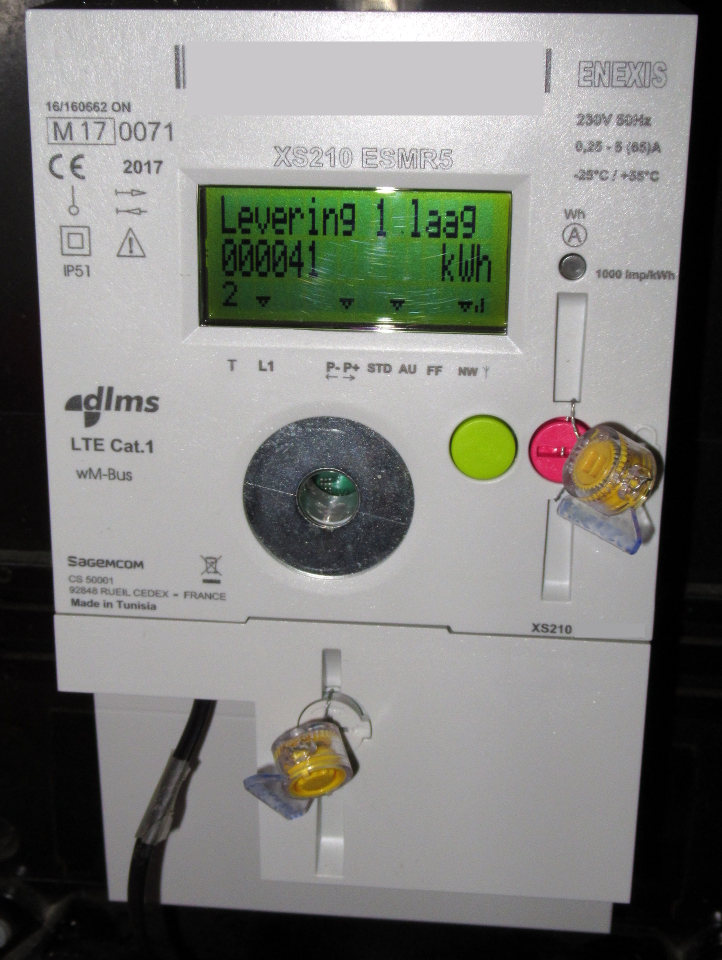
Some weeks ago, new electricity and gas meters were installed. Yes, it was time to install the smart meter variants (‘slimme meter’). Enexis is the distribution network operator and selected in this case the Sagemcom XS210 as smart meter. The great thing of these meters is, that there is a possibility to read out the values (cumulative and current) of these devices using a so called P1-plug. The interfaces (physically and logical) are defined in the Dutch Smart Meter Requirements (DSMR). The Sagemcom XS210 is using version 5.0 of this standard.
In this post you will learn how to create a cable (P1 to USB) to read out these values.
Important: This post is 100% Linux (Ubuntu/OpenWrt), no MS Windows computer needed!
I’m not responsible for any damage you cause at your smart meter or any other device!
Physical description of the P1-interface
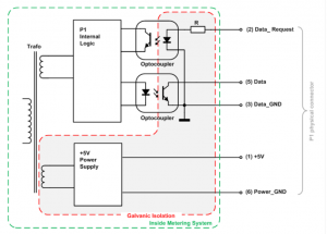
In this paragraph I will cite some passages of the Dutch Smart Meter Requirements (DSMR). And where applicable I will clarify some things. The figure on the left (P1-interface scheme) is copied from the DSMR.
Here we see clearly 3 main parts of the P1-physical connector:
- Possibility to request data (pin 2 and 3);
- The output of the data (pin 5 and 3);
- Power supply for external devices (pin 1 and 6).
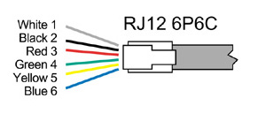
The numbers are referring to the pins of an RJ11 or RJ12-connector. The difference of these two is the number of possible wires, respectively 4 or 6. So you need the latter when you would like to use the built-in power supply. Both should physically fit.
We can read the reasons why it is constructed like this in the DSMR:
“The P1 port lines must be galvanically isolated from the mains, including +5V power supply line. To secure a user of P1 port from electric shock, and at the same time to protect the Metering System against any kind of reversed connection, and to avoid the possibility of influencing the Metering System through the P1 port, all the lines of P1 port must be galvanically isolated from the mains (Including +5V power supply line). To achieve galvanic isolation and to lower the possibility of influencing the Metering System
through the P1 port, the signal lines (Data and Data Request) must be equipped with opto-couplers.”
The nice thing here is also that there is a power supply available at the P1-connector. So we can use P1 also to supply power to third party devices:
“Power supply – The +5V power supply line is meant to provide a power source to OSM (Other Service Module) devices, to enable their ability to process and transfer received metering data further wired or wireless (i.e. via Bluetooth or Wi-Fi technologies).”
“Current characteristics – The power supply must be able to continuously supply current I L_CONT <= 250 mA.”
“The power consumption of the P1 circuitry shall NOT be included in the register values of the Electricity meter.”
Even better, we can use this 250 mA current for free !
Source: P1 Companion Standard, Dutch Smart Meter Requirements, Version 5
Build the interface cable
So let’s build the interface cable between the smart meter and our own device, which will read the data. Actually we will build a P1 to USB cable.
What do we need to build this cable? Check the list below. Costs? The USB to serial cable is the most expensive, let’s say 8-10 euro. The connector is between 1 and 2 euro, resistor and wires some cents. Besides of that we need some tools which you could have or not. Buying them can be quite expensive.
Part list
- USB to serial interface
- RJ11 or RJ12 modular connector
- 1 kΩ resistor
- Some (soldering) tools, wires, heat-shrink etc.
USB to serial cable

Selection of a USB to serial cable – Because of the nature of the P1-interface (open collector), the RxD (receive) signal must be inverted (5 volt = low, 0 volt =high). There are hardware solutions to do this with a transistor, but I chose to do it the easy way without extra electronic components. It is namely possible to reprogram an FTDI chip (eeprom), just by a small utility. So I selected the ‘FTDI Chip, TTL-232R-3V3, USB to TTL Serial Cable (3.3V)‘. And used a Linux utility to reprogram the chip.
So let’s reprogram the FTDI chip.
Install the necessary build tools and libraries:
sudo apt-get install build-essential gcc make libftdi-dev libusb-dev
Retrieve the source code and build the the reprogram utility:
mkdir ~/ftdi_utility && cd ~/ftdi_utility
wget "http://rtr.ca/ft232r/ft232r_prog-1.25.tar.gz"
tar -xzf ft232r_prog-1.25.tar.gz
cd ft232r_prog-1.25
make
Now the utility is ready to use. Insert the FTDI USB to serial cable into your computer and read the current values to make a backup and check whether RxD is not inverted already:
sudo ./ft232r_prog --dump

ft232r_prog: version 1.25, by Mark Lord.
       eeprom_size = 128
         vendor_id = 0x0403
        product_id = 0x6001
      self_powered = 0
     remote_wakeup = 0
suspend_pull_downs = 0
     max_bus_power = 90 mA
      manufacturer = FTDI
           product = TTL232R-3V3
         serialnum = FTXXXXX
   high_current_io = 1
  load_d2xx_driver = 0
      txd_inverted = 0
      rxd_inverted = 0
      rts_inverted = 0
      cts_inverted = 0
      dtr_inverted = 0
      dsr_inverted = 0
      dcd_inverted = 0
       ri_inverted = 0
           cbus[0] = TxDEN
           cbus[1] = TxDEN
           cbus[2] = TxDEN
           cbus[3] = TxDEN
           cbus[4] = TxDEN
No change from existing eeprom contents.
Important here is the value for ‘rxd_inverted’ which is ‘0’ and should be ‘1’. To accomplish this, execute this command:
sudo ./ft232r_prog --invert_rxd
You eventually could check the result, using the ‘–dump’ command again. Now the FTDI chip is ready for your meter.
Wire the USB to serial cable and RJ11/12 connector
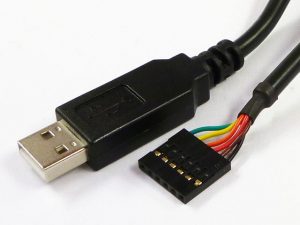
At the moment we have a USB to serial cable, and an RJ11 or RJ12 connector. But how to wire these together?
Let’s first summarize the pinouts of the USB to serial cable and the RJ11 / RJ12 connector.
In this case we don’t use the power supply of the P1 connector, so both RJ11 and RJ12 connectors are usable. When you use the RJ11 connector, assume there are 2 virtual extra wires at the outside (1 and 6). When counting, keep the tip at the top and count from the right (1) to left (6).
Assumed you know how to work with (soldering) tools and heat-shrink, make the following connections:
- You have to connect both signal grounds (GND),
- make data request high (+5V) so that data is requested continuously (every 1 second) and
- connect data of P1 to RxD of the ‘USB to serial’-cable.
| Name | USB to serial | P1 |
|---|---|---|
| Signal ground (GND) | Black (1) | 3 |
| Data (RxD) | Yellow (5) | 5 |
| Data request | Red (3) | 2 |

Important: Besides of that you have to connect a pull-up resistor of 1kΩ between +5V of the ‘USB to serial cable’ (red wire) to RxD (yellow or pin 5). This is because of the construction of the P1 interface (data connection is an open collector). It is possible that this resistor is not needed at other smart meters. At the ‘Sagemcom XS210’ it is at least necessary.
Read data from smart meter
Now the real fun part can start or a.k.a. testing the P1-to-USB-cable: Reading data from your smart meter!
Plug in the USB connector to your computer and the RJ11/12 connector to the P1-connector of the meter.
At a Linux based computer you should read something like this, when you issue the ‘dmesg’ command:
[   17.850000] usbcore: registered new interface driver ftdi_sio
[   17.860000] usbserial: USB Serial support registered for FTDI USB Serial Device
[   17.880000] ftdi_sio 2-1:1.0: no of_node; not parsing pinctrl DT
[   17.880000] ftdi_sio 2-1:1.0: FTDI USB Serial Device converter detected
[   17.890000] ftdi_sio ttyUSB0: no of_node; not parsing pinctrl DT
[   17.890000] usb 2-1: Detected FT232RL
[   17.900000] usb 2-1: FTDI USB Serial Device converter now attached to ttyUSB0
Here you see that the ‘ftdi_sio’ driver (module) is used. Of course this module must be available at your system. Besides of that you can read that the device name is ‘ttyUSB0’.
In the specifications of this smart meter ‘Sagemcom XS210’ is mentioned that data is send at 115200 baud, 1 start bit, 8 data bits, no parity bit and 1 stop bit. This is also known as “8N1”. Because of the ‘request data’-pin is always high in our set up, it must be sending data already. Let’s try to receive this data.
At other smart meters sometimes lower speeds (i.e. 9600) and 7 data bits are used.
You can receive this data by a terminal application, which connects to the serial port. Examples of these applications are ‘minicom’ and ‘socat’. Assumed you have installed ‘socat’ at your system, issue this command to dump the output to standard out:
sudo socat - FILE:/dev/ttyUSB0,b115200
When ‘dmesg’ in a previous step mentioned another device (not ttyUSB0), use that one. Speed is set to 115200 baud. Use ‘sudo’ to be allowed to read this device or add the logged in user to the correct (‘dialup’?) group.
The output should look something like this:
/Ene5\XS210 ESMR 5.0

1-3:0.2.8(50)
0-0:1.0.0(170916191108S)
0-0:96.1.1(Equipment identifier electricity)
1-0:1.8.1(000000.001*kWh)
1-0:1.8.2(000000.002*kWh)
1-0:2.8.1(000000.004*kWh)
1-0:2.8.2(000000.000*kWh)
0-0:96.14.0(0001)
1-0:1.7.0(00.005*kW)
1-0:2.7.0(00.000*kW)
0-0:96.7.21(00006)
0-0:96.7.9(00007)
1-0:99.97.0(1)(0-0:96.7.19)(000000000)(0000000009*s)
1-0:32.32.0(00000)
1-0:32.36.0(00000)
0-0:96.13.0()
1-0:32.7.0(227.0*V)
1-0:31.7.0(000*A)
1-0:21.7.0(00.008*kW)
1-0:22.7.0(00.000*kW)
0-1:24.1.0(003)
0-1:96.1.0(Equipment identifier gas)
0-1:24.2.1(000000)(00000.0010*m3)
!0F2E
This is a so called P1 telegram. (I modified it, for privacy reasons.) There are many fields available. For a normal user, here is a list of important fields:
| Field code / OBIS* reference | Description |
|---|---|
| 0-0:1.0.0 | Date-time stamp of the P1 message |
| 1-0:1.8.1 | Meter Reading electricity delivered to client (Tariff 1) in 0,001 kWh |
| 1-0:1.8.2 | Meter Reading electricity delivered to client (Tariff 1) in 0,001 kWh |
| 1-0:2.8.1 | Meter Reading electricity delivered by client (Tariff 1) in 0,001 kWh |
| 1-0:2.8.2 | Meter Reading electricity delivered by client (Tariff 2) in 0,001 kWh |
| 1-0:1.7.0 | Actual electricity power delivered in 1 Watt resolution |
| 1-0:2.7.0 | Actual electricity power received in 1 Watt resolution |
| 0-1:24.2.1 | Last 5-minute value (temperature converted), gas delivered to client in m3 |
*) OBIS: Object Identification System.
User friendly usage
Now you created your own cable and are able to read data from the smart meter! The next part of this article is not a step by step guide, it will give you just some hints how to implement this in a user friendly way.
As you can see, reading a P1 telegram is not user friendly. So I decided to place a small/cheap embed linux device (running OpenWrt) near the smart meter, which is connected using the self-built USB-P1-cable with the smart meter and wireless with the local wifi-network. At another computer a Domoticz instance is running which is accessible via a web browser or (Android) app. Of course you could also decide to place a Raspberry Pi near the smart meter and run Domoticz at the Raspberry Pi. In this article however I will explain obtaining the P1-telegrams from a remote network device.
Configuring a remote node which will relay P1 telegrams to a local network
In short: Use ‘socat’ to relay the virtual serial port (ttyUSB0) to a TCP port (1234)
socat TCP-LISTEN:1234,fork,reuseaddr FILE:/dev/ttyUSB0,b115200
I selected as embed linux device an unbranded Ralink/MediaTek RT5350F based router device, the printed circuit board has the tag: A5-V11. At Dealextreme you have to search for ‘3g 4g router’. Price is +/- 8 euro.
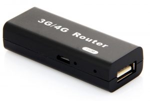 At this device I installed a new boot-loader and my own built OpenWrt. This is an advanced procedure, which is just described globally in this article. Read instead at the OpenWrt more about this device and installation instructions.
Read also at the OpenWrt site how to install the Image Generator.
Hint: You need to download the image generator (builder) for ramips/rt305x and run at a 64 bits linux system as non root user. Select as profile: A5-V11 and install as extra packages the FTDI-driver (kmod-usb-serial-ftdi) and ‘socat‘ as command line terminal application. You can also install ‘minicom’ for testing purposes.
sudo apt-get install subversion build-essential libncurses5-dev zlib1g-dev gawk git ccache gettext libssl-dev xsltproc wget
mkdir ~/openwrt && cd ~/openwrt
wget "https://downloads.openwrt.org/chaos_calmer/15.05.1/ramips/rt305x/OpenWrt-ImageBuilder-15.05.1-ramips-rt305x.Linux-x86_64.tar.bz2"
bunzip2 OpenWrt-ImageBuilder-15.05.1-ramips-rt305x.Linux-x86_64.tar.bz2
cat OpenWrt-ImageBuilder-15.05.1-ramips-rt305x.Linux-x86_64.tar | tar x
cd OpenWrt-ImageBuilder-15.05.1-ramips-rt305x.Linux-x86_64
make image PROFILE=A5-V11 PACKAGES="kmod-usb-serial-ftdi socat minicom"
Find at: ‘bin/ramips/openwrt-15.05.1-ramips-rt305x-a5-v11-squashfs-sysupgrade.bin’ the newly build OpenWrt-image for your device.
Put at the root of a FAT formated USB-stick the just created OpenWrt-sysupgrade-image and name it: firmware.bin
Besides of that put the correct bootloader at the USB-stick.
Now insert the USB-stick into the A5-V11 device, mount the stick (make mountpoint and mount) and write the bootloader to the ‘Bootloader’ partition using the command ‘mtd_write’ (see /proc/mtd) and the firmware.bin to the appropriate partition. See the OpenWrt site for more information.
Assumed you successfully installed your own OpenWrt including the extra packages at the A5-V11 device, you can now login as root to the prompt. Connect the USB-P1 cable like you did at a normal computer (don’t forget to connect it to the meter too), check ‘dmesg’ whether the cable is detected (FTDI module is loaded: ‘lsmod’) and what the new device is (i.e ttyUSB0). Now you can execute the command:
socat - FILE:/dev/ttyUSB0,b115200
When you are receiving the P1 telegram, everything is ok. Stop ‘socat’.
Now add the line:
socat TCP-LISTEN:1234,fork,reuseaddr FILE:/dev/ttyUSB0,b115200 &
to /etc/rc.local just before ‘exit 0’. This will start ‘socat’ everytime OpenWrt starts. Socat will listen at TCP port 1234. When you connect to this port from another computer, you will see the P1 telegram. Make sure your OpenWrt-device has network connectivity (LAN of WAN). Configuring network connectivity is beyond the scope of this article. Read here how to configure the network of OpenWrt: English or Dutch.
Now you are ready at the OpenWrt-device. Restart it and leave it running. You can test it by connecting by telnet to the IP address and port 1234 of this device.
Domoticz
In this article I won’t describe how to install Domoticz, read at the Domoticz website how to install it.
After you installed Domoticz, point your web browser to it. Default running at port 8080.
- Open Setup->Hardware;
- Select as Type (pull down menu): ‘P1 Smart Meter with LAN interface‘;
- Set ‘Data Timeout‘ to 5 minutes;
- ‘Remote Address‘ to the IP-address of the device running ‘socat’ (which is bridging between P1 and the network);
- Set ‘Port‘ to the TCP port socat is listening at (i.e. 1234);
- Keep ‘CRC message validation‘ on;
- Set ‘Rate Limit‘ i.e. to 600 seconds.;
- Click Add.

After a short time, you will find in Domoticz -> Setup -> Devices a list of found devices at your smart meter. In this image you see three devices, from top to bottom: the electricity (power) consumption, the measured voltage and the gas consumption.

Just let this set up run for some time. To see the power (electricity) consumption over time, click in Domoticz: ‘Utility‘ and the ‘Log‘ button at the ‘Power’-tile.
Read more
- Slimme meter uitlezen met Raspberry Pi (NL)
- P1 poort slimme meter (hardware) (NL)
- New smart meter installed (Iskra ME382 and Landis + Gyr gasmeter E06140)
- Data sheet FTDI cable
- OpenWrt article about the A5-V11 / 3G, 4G router
- Wikipedia – Smart meter
- Wikipedia – Pull up resistor
- Wikipedia – Heat shrink tubing
